Barometric altitude measurement is commonly found on most flight computers. There are however several problems associated with this type of measurement. First of all, disturbances in air pressure can occur close to the nosecone or near transitions in the air frame. In addition, transition to supersonic flight may give rise to shockwaves that could lead to false altitude readings. Finally, accurate altitude calculations are not possible at higher altitudes.
Calculation of altitude and apogee is also possible by measuring acceleration, a parameter that is not easily influenced by other factors. By integrating acceleration over time, it is possible to calculate vertical velocity and altitude. This system for determining apogee was widely used in the RDAS flight computers of the Dutch company AED electronics. Although the last version of the RDAS tiny is still being used by NERO, the drivers for this flight computer are no longer supported, and special procedures need to be followed to get the old non-licensed drivers working together with recent versions of Windows.
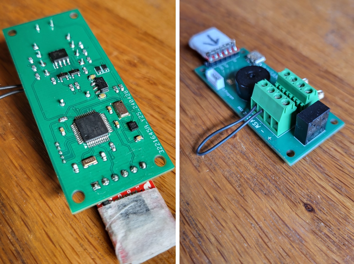
To overcome these problems with the RDAS, a new flight computer was designed that also uses acceleration to determine apogee. For this, the modern KX134 accelerometer was used, capable of measuring up to 64G’s in three axes. Deployment of the main parachute at lower altitudes is determined by barometric altitude measurement using a MS5611 barometric sensor. To facilitate easy data transfer, the board is equipped with a Openlog (Sparkfun) SD card logger. Testing of the new flight computer will start this summer.
The second launch day of the year started out with overcast skies with an occasional drizzle. Fortunately, the wind was weak and coming from a N/ NE direction.
This time we were particularly eager to set up our launch tower without any deviations in azimuth (55 degrees) and elevation (83 degrees). No corrections were needed upon inspection by the commanding officer. A good thing, as the launch window was approaching quickly.
The intimidator rocket was again quickly assembled by JvdB and mounted in the launch rail well in time for the upcoming launch window. The GPS tracking electronics was briefly activated to allow for a GPS lock, enabling a warm start of the system upon activation for launch. The system obtained a lock within just a few seconds which was a bit of a relief. The system did not fly before and testing at home is always different than in an actual launch situation. Luckily the ASK factor did not play tricks on us this time and everything appeared nominal.
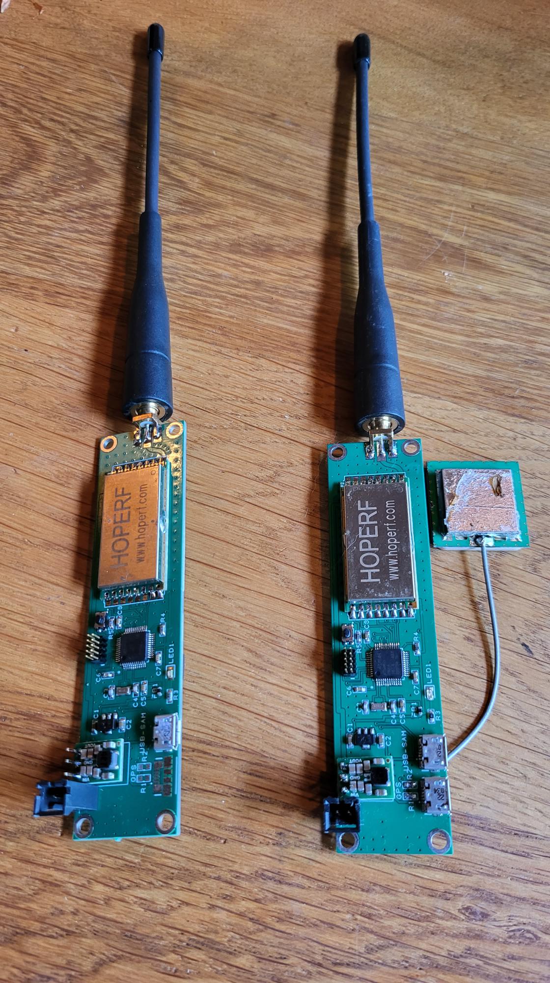
Lora GPS transmitter
After some last-minute doubts about shock cords, we decided that the Intimidator rocket was good to go. It was the nineth time we launched this rocket in a period of 10 years, so it was a bit of an anniversary. Over these years, the Intimidator has been used for testing new concepts and electronics. Next to the new GPS tracking hardware, the rocket was now also equipped with a new APCP motor designed and built by JvdB.
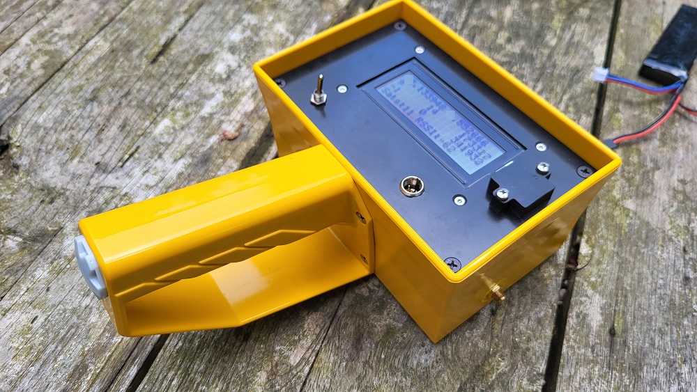
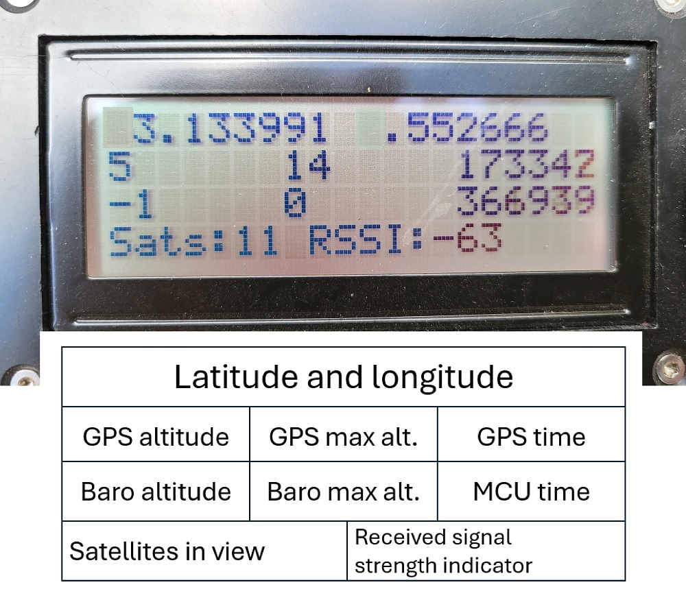
Handheld ground stationClose-up of the screen showing the most important data. GPS data is relayed through bluetooth to the Rocket Locator App
After arming the rocket, we quickly drove up to the viewing area to obtain a clear view of the launch area. This proved to be challenging as the student teams Aquilo and Rise were accompanied by many spectators. After finding a private spot, the handheld tracking receiver was activated which started sending GPS data to the Rocket Locator App on my phone. The LORA data transfer is relatively slow, and updates were received approximately every 5 seconds.
After a quick countdown, the APCP motor quickly started and propelled the rocket out of the tower with a mighty roar. The rocket strongly accelerated in a straight line and quickly disappeared into the clouds.
Slow motion of the launch
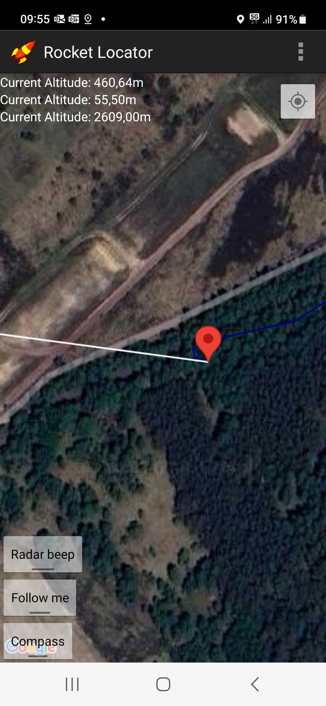
Rather than staring at the clouds, the rocket could now be tracked on the phone. Altitude was reported throughout the flight and the position was plotted onto a map of the area in the Rocket Locator App. Everything appeared to go as planned, and apogee was reached at 2619 meters. However, the descent velocity was much lower than the expected 30m/s of the drogue less design, indicating that the main had come out at apogee.
Screenshot showing the rocket landing site in Rocket Locator. Unfortunately, the App is no longer updated and contains a few bugs (distance, current altitude and max altitude not properly indicated in the top left). App is also no longer available in the Android Play store.
The trip down was slow and the winds at higher altitude threatened to push our rocket out of the desired landing area. Luckily winds were less strong and parallel to the field at lower altitudes. Finally, the rocket and parachute appeared from the clouds, exactly at the position indicated by Rocket Locator. However, it was clear that a landing in the trees was inevitable.
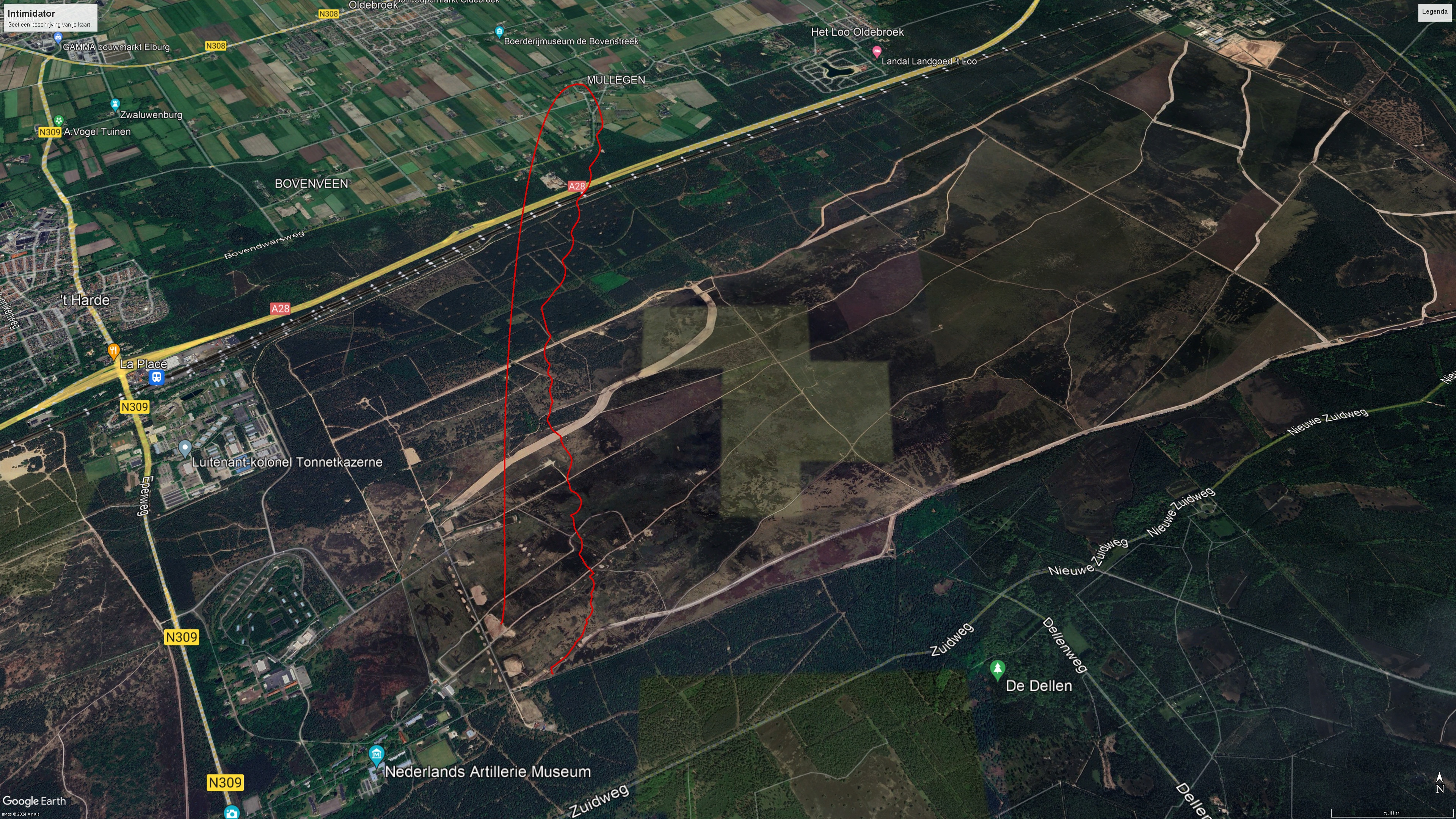
GPS track of the Intimidator flight (shown in red)
Recovery was easy as the parachute and rocket could be released from the trees with a gentle tug. Flight 9 was successful and the Intimidator is still in good shape for a 10th launch!
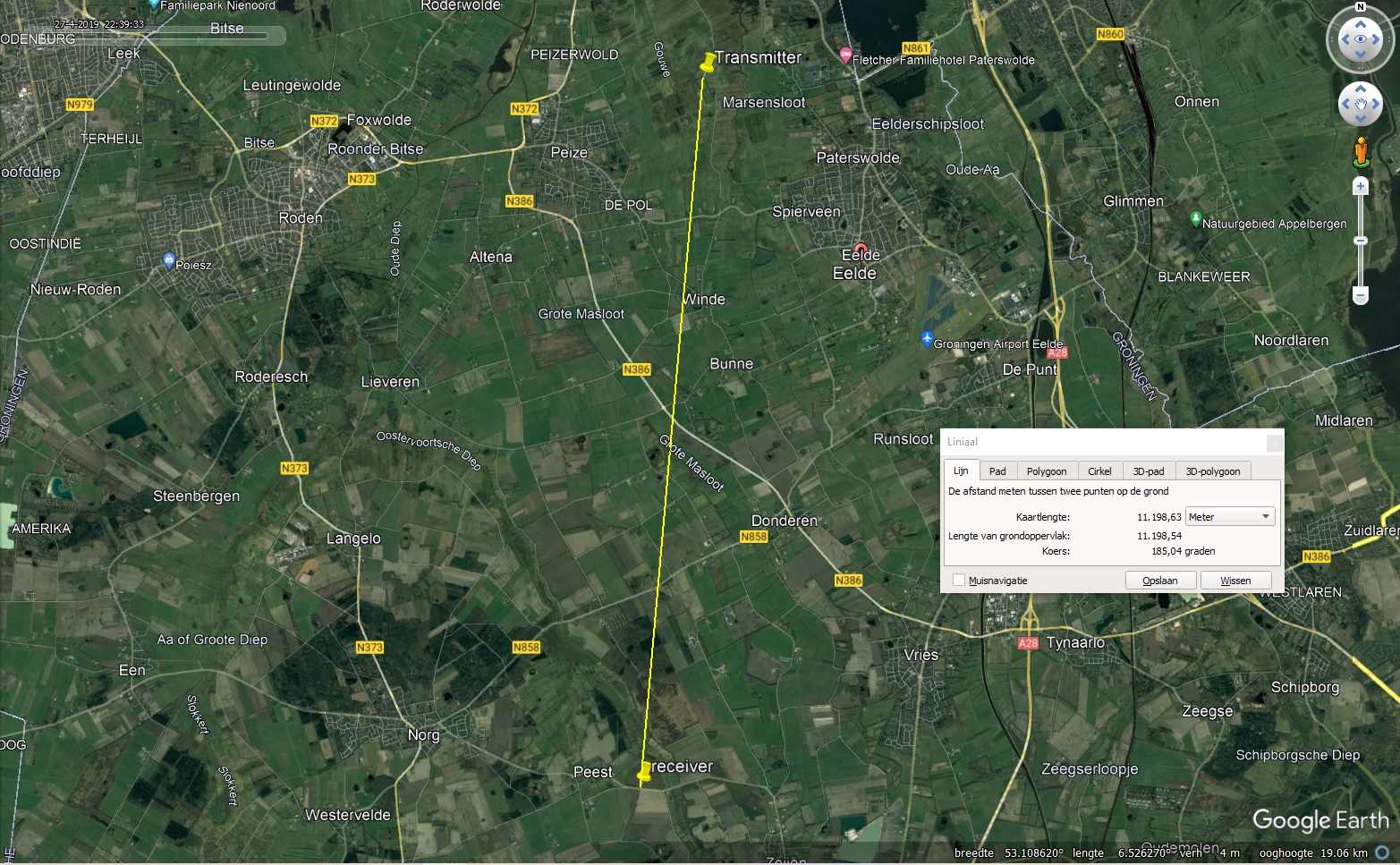
Transmitter was mounted on top of observation tower (26 meters). Receiver equipped with yagi antenna successfully received all packages at ground level at 11.2km distance!
As there are more modern options to reliably transmit data to a ground station, I decided to switch from Talky to a HopeRF RFM98PW Lora module. This module is max 1 watt and can be easily implemented using the Arduino Radiohead library.
In addition, the trusted Atmega 328P has been replaced by the faster SAMD21G MCU with more memory and an embedded USB port/
Barometric pressure is measured using a MS5611 unit
Finally, the quectel L96 GPS unit has been replaced by a Ublox neo-9. This unit has better dynamic properties and allows for a maximum altitude of 80kms.
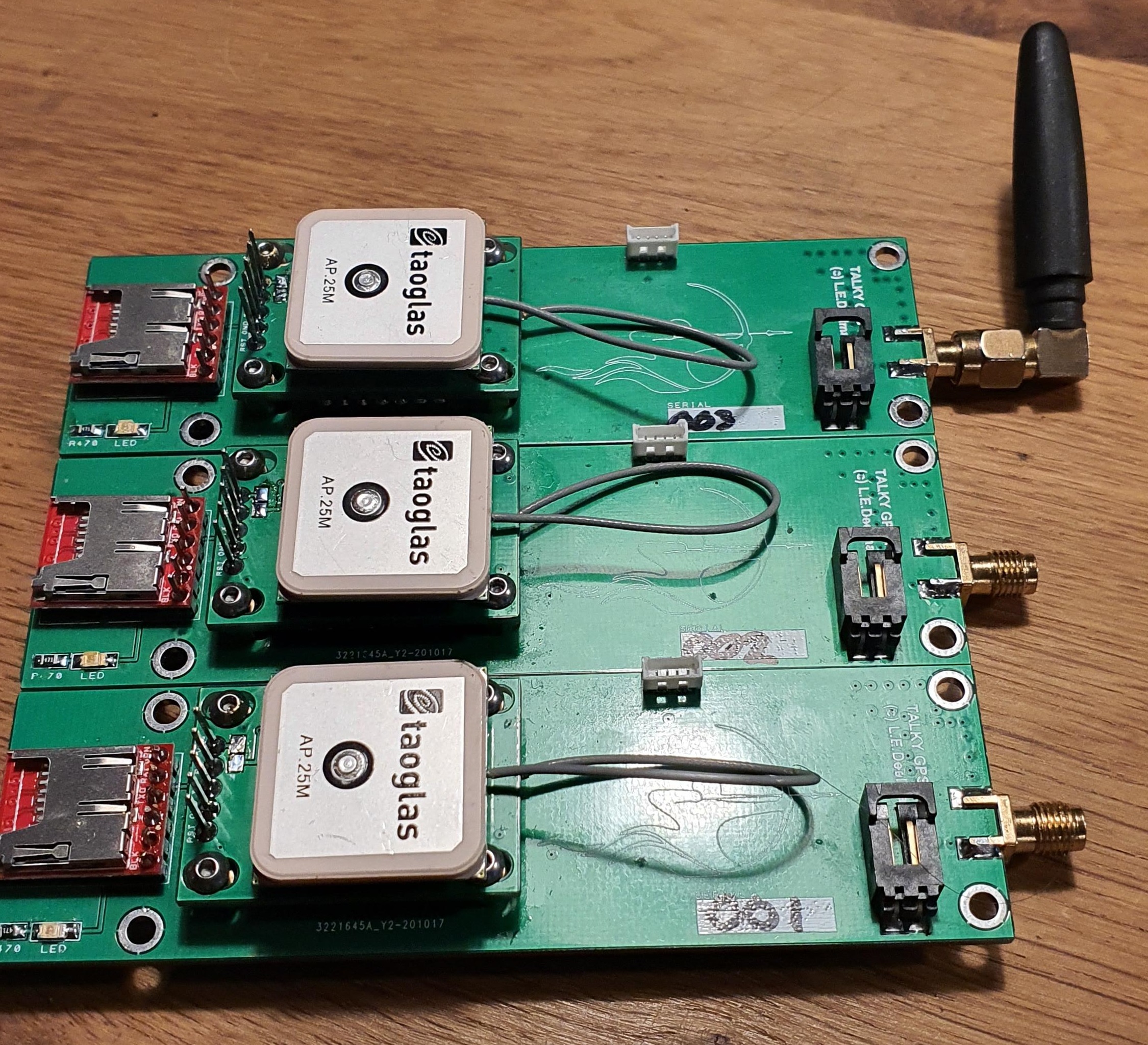
Latest Talky version (3.0). First series of 3 units using low voltage (1S lipo). GPS piggy-back board is now equiped with a Quectel L96 unit in balloon mode. Factory specs indicate a maximum altitude of 80km, but GPS spoofing experiments suggest maximum altitude of approximately 120km and a max speed of 2000m/s.
Prior to the anticipated launch in October we performed a full assembly of the Boostar- Giga stack. The test session did not reveal any ´surprises´ and total assembly took less than an hour.
Update (9 Oct 2020): Due to corona related travel restrictions we decided to postpone our launch until spring 2021.
The Boostar two solid APCP rocket motor was successfully tested on the 4th of May 2020. The motor produced a thrust up to 7500N with an overall performance of 43kNs.
20+ kgs of propellant was mixed in a A200 Hobart mixer in two batches of 10 kgs.
Degassing of the mixture using a high vacuum
For casting of the propellant, a modifiedhobart mixer bowl was used with a plugable opening in the bottom. This allows for a mess-free filling of the casting tube.
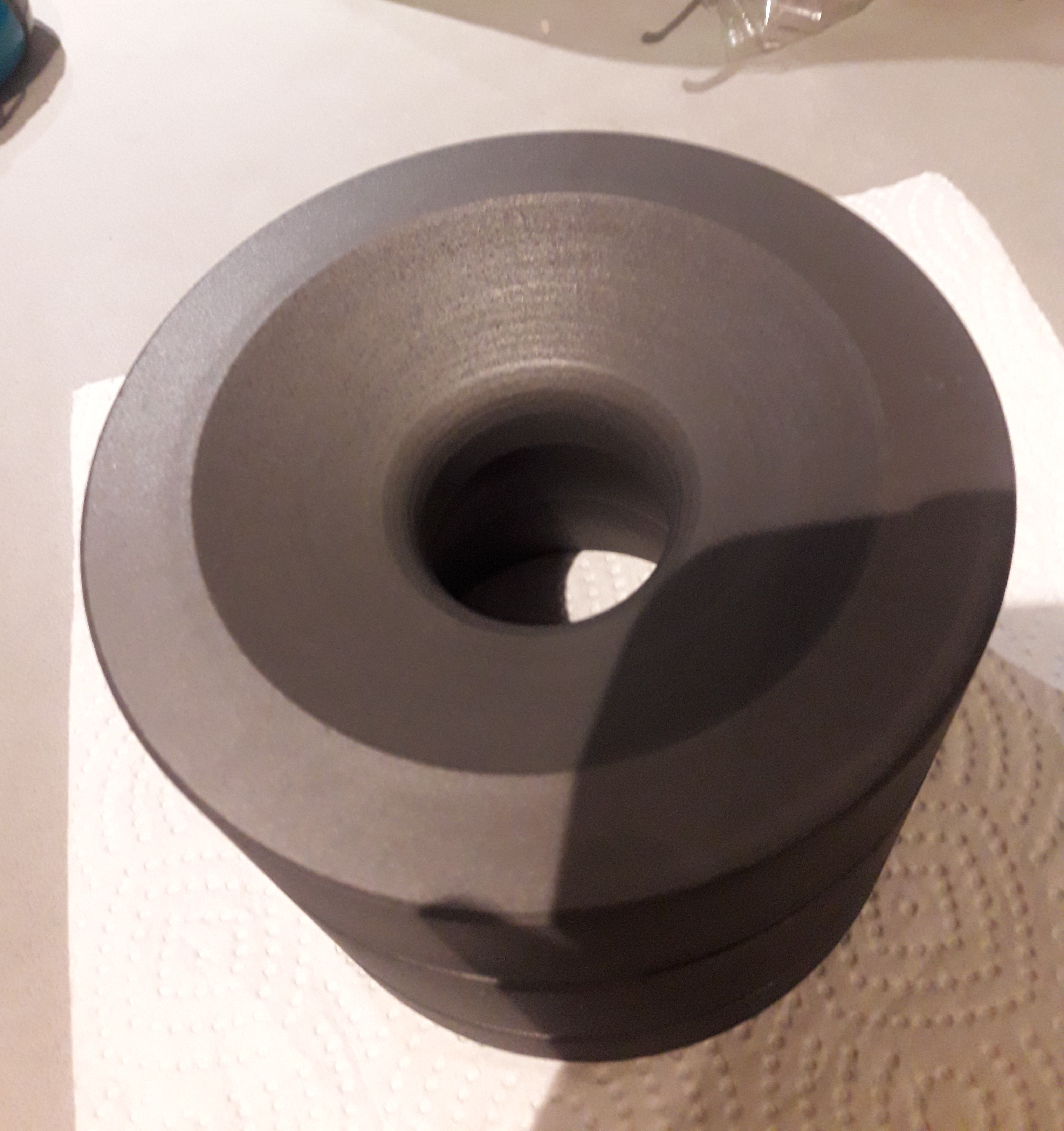
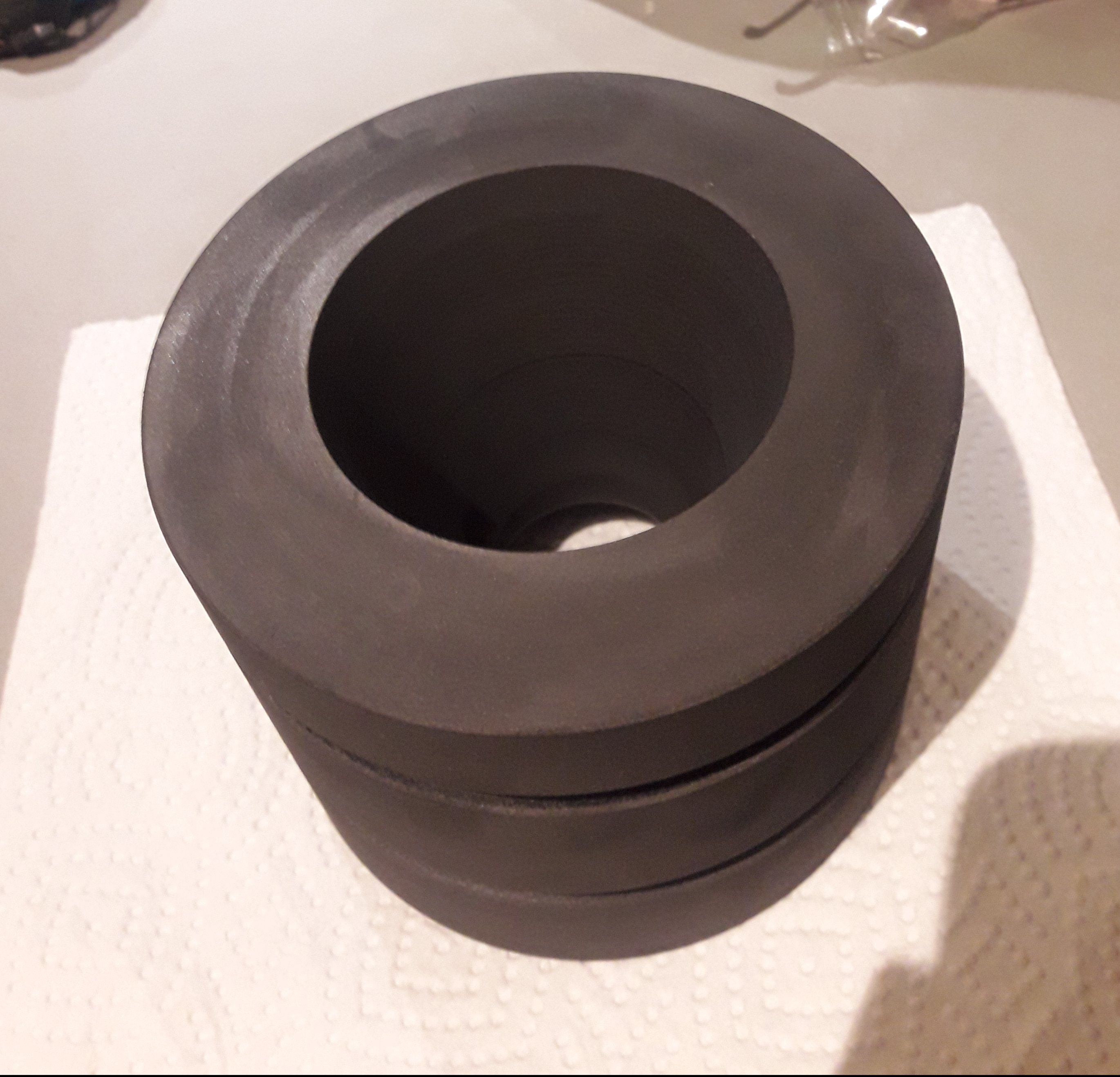
After curing for several days, the lower plug of the casting tube was removed to reveal the nice star shaped XPS core supported by a 30mm aluminium rod.
Subsequently, the propellant was glued into the 130×5 casing using HTPB to avoid any air between liner and casing.
After curing of the HTPB for several days, the XPS core will be dissolved by a mixture of acetone and xylol.